Staying the Course during Underwater Repairs
Underwater wet welding was used to permanently repair a crucial part of a vessel’s propulsion system By Uwe W. Aschemeier, senior welding engineer and Kevin S. Peters, director of technical sales & Asia-Pacific operations, for Subsea Global Solutions, Miami, Fla. Reprinted with permission: The AWS Welding Journal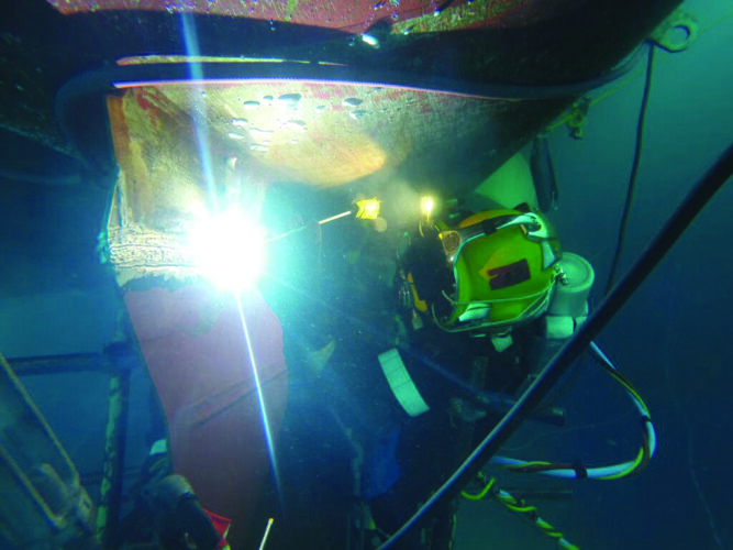 In the maritime world, a propulsion system is defined as a unit used to provide thrust to enable a vessel to move across water. Mechanical marine propulsion systems consist of electric motors or engines that turn propellers. After ships had been moved by paddles and sails for centuries, marine steam engines were introduced, making them the first engines used in marine propulsion. Steam engines have since been replaced in modern ships by diesel engines and gas turbine engines on faster ships. Electric motors fueled by electricity stored in batteries provide energy-efficient propulsion for submarines and electric boats.
Liquefied natural-gas-fueled engines also provide economic advantages and low emissions. Propulsion systems that are in use today, or are in a research state, include diesel, wind, nuclear, gas turbine, fuel cell, solar, steam turbine, diesel-electric, waterjet, and gas fuel propulsion. Propulsion systems often require repair from damage as a result of loads and stresses, such as severe weather and erratic maneuvers. The following story describes the permanent repair of a crucial component on a cruise ship’s propulsion system using underwater wet welding techniques. To keep the ship en route, the repair was performed during regularly scheduled port stops without interrupting the vessel’s itinerary.
A Damaged Skeg
Following its departure from Miami, Fla., a cruise ship experienced a grounding, which is the impact of a ship on the seabed or waterway side. After being contacted, Subsea Global Solutions (SGS), an underwater ship maintenance and repair provider, deployed a dive team to inspect the damage during the ship’s next port of call in the Caribbean. The inspections discovered the starboard Azipod® skeg was torn off just below the weld between the skeg and the cofferdam at the interface to the Azipod gear housing.
The Azipod is a marine propulsion unit consisting of a fixed pitch propeller mounted on a steerable gondola (the pod). The pod contains the electric motor driving the propeller. A fin (skeg) is usually mounted underneath the pod to increase maneuverability and fuel efficiency; this is the part that was torn.
However, the skeg was not completely torn off the cofferdam bulkhead, as the skeg material was still connected in some areas to the bottom plate of the cofferdam underneath the gear housing of the Azipod. The cofferdam and the associated weld joint between the cofferdam and the gear housing of the Azipod were undamaged.
Proposed Repair Solution
Before beginning the repair, an extensive document was created describing the planned approach. It listed all necessary documentation required to facilitate an underwater wet weld repair, including welder qualifications, procedure qualification records, welding procedure specification, and chemical analyses of materials to be welded.
After the vessel’s owner and the original equipment manufacturer (OEM) of the Azipod agreed to the proposed repair approach, the next step was to submit the detailed repair procedure to the ship’s classification society for review and approval. Classification societies are nongovernmental organizations that establish and maintain technical standards for the construction and operation of ships and offshore structures.
The proposed solution involved a permanent repair of the damaged skeg by removing the remaining skeg plating, including the weld joints, from the cofferdam using hydrogouging, as well as installing a new skeg by employing underwater wet welding techniques and procedures approved by GL (now DNV GL) to Class A in accordance with the American Welding Society (AWS) D3.6M, Underwater Welding Code.
The repair was scheduled during regular port stops without interrupting the itinerary of the vessel. It was planned (and performed) as follows:
In the maritime world, a propulsion system is defined as a unit used to provide thrust to enable a vessel to move across water. Mechanical marine propulsion systems consist of electric motors or engines that turn propellers. After ships had been moved by paddles and sails for centuries, marine steam engines were introduced, making them the first engines used in marine propulsion. Steam engines have since been replaced in modern ships by diesel engines and gas turbine engines on faster ships. Electric motors fueled by electricity stored in batteries provide energy-efficient propulsion for submarines and electric boats.
Liquefied natural-gas-fueled engines also provide economic advantages and low emissions. Propulsion systems that are in use today, or are in a research state, include diesel, wind, nuclear, gas turbine, fuel cell, solar, steam turbine, diesel-electric, waterjet, and gas fuel propulsion. Propulsion systems often require repair from damage as a result of loads and stresses, such as severe weather and erratic maneuvers. The following story describes the permanent repair of a crucial component on a cruise ship’s propulsion system using underwater wet welding techniques. To keep the ship en route, the repair was performed during regularly scheduled port stops without interrupting the vessel’s itinerary.
A Damaged Skeg
Following its departure from Miami, Fla., a cruise ship experienced a grounding, which is the impact of a ship on the seabed or waterway side. After being contacted, Subsea Global Solutions (SGS), an underwater ship maintenance and repair provider, deployed a dive team to inspect the damage during the ship’s next port of call in the Caribbean. The inspections discovered the starboard Azipod® skeg was torn off just below the weld between the skeg and the cofferdam at the interface to the Azipod gear housing.
The Azipod is a marine propulsion unit consisting of a fixed pitch propeller mounted on a steerable gondola (the pod). The pod contains the electric motor driving the propeller. A fin (skeg) is usually mounted underneath the pod to increase maneuverability and fuel efficiency; this is the part that was torn.
However, the skeg was not completely torn off the cofferdam bulkhead, as the skeg material was still connected in some areas to the bottom plate of the cofferdam underneath the gear housing of the Azipod. The cofferdam and the associated weld joint between the cofferdam and the gear housing of the Azipod were undamaged.
Proposed Repair Solution
Before beginning the repair, an extensive document was created describing the planned approach. It listed all necessary documentation required to facilitate an underwater wet weld repair, including welder qualifications, procedure qualification records, welding procedure specification, and chemical analyses of materials to be welded.
After the vessel’s owner and the original equipment manufacturer (OEM) of the Azipod agreed to the proposed repair approach, the next step was to submit the detailed repair procedure to the ship’s classification society for review and approval. Classification societies are nongovernmental organizations that establish and maintain technical standards for the construction and operation of ships and offshore structures.
The proposed solution involved a permanent repair of the damaged skeg by removing the remaining skeg plating, including the weld joints, from the cofferdam using hydrogouging, as well as installing a new skeg by employing underwater wet welding techniques and procedures approved by GL (now DNV GL) to Class A in accordance with the American Welding Society (AWS) D3.6M, Underwater Welding Code.
The repair was scheduled during regular port stops without interrupting the itinerary of the vessel. It was planned (and performed) as follows:
- Removal of the remaining skeg plating;
- Preparing the cofferdam underneath the Azipod housing for welding;
- Preparing the new skeg for installation;
- Performing a test run of the installation to ensure proper fitup of the weld joint;
- Installing the skeg;
- Performing nondestructive examination (NDE) on welds; and
- Applying corrosion protection.
- The cofferdam underneath the Azipod was of a higher tensile steel DH 36, 30 mm thick;
- The cofferdam bottom plate was also of a higher tensile steel DH 36, 30 mm thick; and
- The skeg plating was of ordinary hull steel Grade A, 10 mm thick.